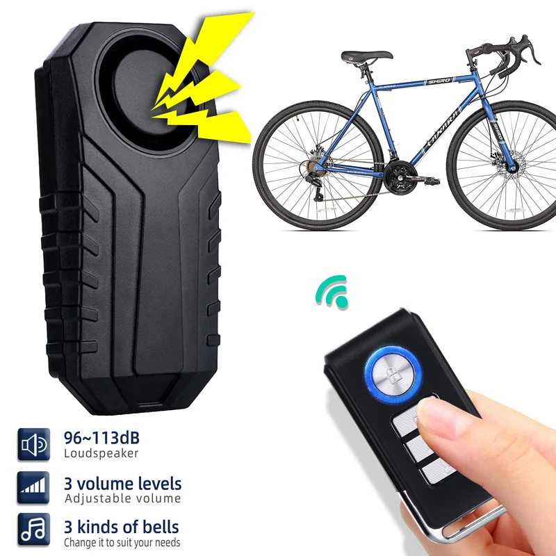
Description
 LED Breathing Light Simulated Firefly Flashing Robot Toys Part Electronic Photosensitive Mobile Robot Soldering DIY KitUSD 3.32/piece
 Light Cube DIY kit RGB LED 51 MCU Electronic Charging Colorful Music 3D Animation Ornament with Remote Control For SolderingUSD 5.57/piece
 2 PCS DIY Flashing LED Kit Electronic Circuits Multivibrator IC Welding Training Suite DIY Soldering Teach Training IC PartsUSD 1.61/piece
 76-108MHz FM Stereo Radio DIY Kit Wireless FM Radio Transmitter and Receiver Module Frequency Modulation Soldering PracticeUSD 0.99-2.15/piece
 DIY Electronic Kit LED Rotating Ferris Wheel Circuit Rotary Colorful LED Remote Infrared Control 10 Kinds Flashing Mode 4.5-5.5VUSD 11.62/piece
 HV-1 High Voltage Igniter Kit Arc Ignition Parts DIY Kit Arc Generator Arc Cigarette Igniter Module PCB Board DC 3-5V 3AUSD 2.85/piece
|
Component |
Number |
Parameter |
Quantity |
|
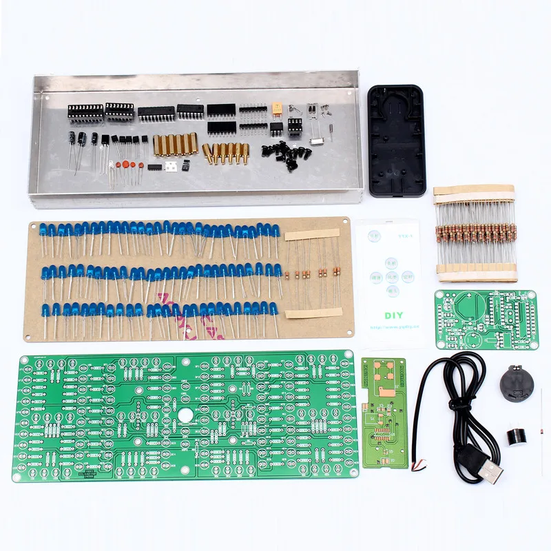
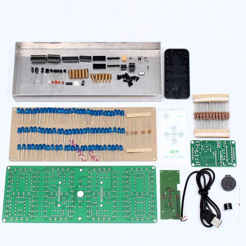
Remote control list: |
|||
|
IC BA5104 |
U1 |
SOP-16 |
1 |
|
S8050 |
Q1 |
SOT-23 |
1 |
|
0805 Capacitor |
C1,C2 |
100pF |
2 |
|
Electrolytic capacitor |
C3 |
22uF 25V |
1 |
|
455E Crystal |
Y1 |
1 |
|
|
Infrared Emitting LED |
D1 |
3mm |
1 |
|
CR2025 Battery shrapnel |
J1 |
2 |
|
|
Screw |
M1.4*3 |
5 |
|
|
PCB |
76*30.5mm |
1 |
|
|
Key Foil |
83*38mm |
1 |
|
|
Shell |
86*40*6mm |
1 |
|
|
Clock control kit list: |
|||
|
Metal film resistor |
R1-R8 |
10K |
8 |
|
Ceramic capacitor |
C6,C7 |
5pF |
2 |
|
Ceramic capacitor |
C4,C5 |
30pF |
2 |
|
Ceramic capacitor |
C3 |
0.01uF |
1 |
|
Electrolytic capacitor |
C1 |
10uF 25V |
1 |
|
Electrolytic capacitor |
C2 |
100uF 16V |
1 |
|
1N4148 |
D1 |
DO-35 |
1 |
|
S8550 |
Q1-5 |
TO-92 |
5 |
|
Crystal |
Y2 |
32.768KHz |
1 |
|
Crystal |
Y1 |
12MHz |
1 |
|
STC11F04E |
U1 |
DIP-20 |
1 |
|
DS1302 |
U2 |
DIP-8 |
1 |
|
74HC138N |
U3 |
DIP-16 |
1 |
|
DIP-8 IC Socket |
U1 |
1 |
|
|
DIP-16 IC Socket |
U2 |
1 |
|
|
DIP-20 IC Socket |
U3 |
1 |
|
|
Buzzer |
LS1 |
5V |
1 |
|
VS1738 Infrared receiver |
U4 |
1 |
|
|
CR2025 battery box |
BT1 |
1 |
|
|
1*8P Female pin |
J2A,J3A |
2.54mm |
2 |
|
USB cable |
80cm |
1 |
|
|
PCB |
70*43mm |
1 |
|
|
Shopping cart
Sign in
No account yet? Create an Account
WhatsApp us
|


